
What Goes Into Designing, Verifying and Proof Testing a Lifting Beam
A lifting beam is a load-bearing engineered system, not simply a fabricated steel member. Its design and acceptance require a defined load path, verified structural capacity, suitable materials and connections, controlled fabrication, inspection and proof testing.
Lifting beams are used to control how loads are transferred between a crane and the item being lifted. Although the equipment may appear straightforward, its design involves multiple load effects and safety considerations that must be assessed before it is placed into service.
The process begins with a clearly defined lifting duty. Engineers need to understand the maximum lifted mass, centre of gravity, lifting-point locations, sling arrangement, crane connection and any possible unequal distribution of load. The intended orientation of the beam and the risk of side loading or out-of-plane loading must also be considered.
The rated capacity alone does not define the complete design condition. Appropriate dynamic or lifting factors may be applied to account for the behaviour of the load during hoisting. Additional load cases may be required for proof testing, handling, transportation or foreseeable off-design conditions. The applicable requirements depend on the equipment type, jurisdiction and project specification.
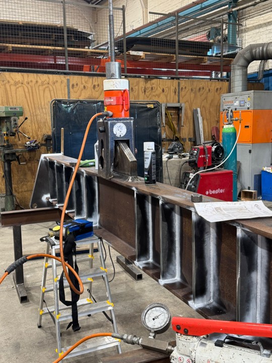
For CITA Engineering’s 35-tonne lifting-beam project, the design process included mechanical and structural calculations together with finite element analysis. The load path was assessed from the lower lifting points through the main beam and connection details to the crane interface.
Several failure modes need to be examined. These may include global bending, shear, local bearing, buckling, lateral instability, weld capacity, pin bending, hole deformation and failure around lifting lugs or connection plates. Deflection also matters because excessive deformation can affect load stability and alter the forces within the lifting arrangement.
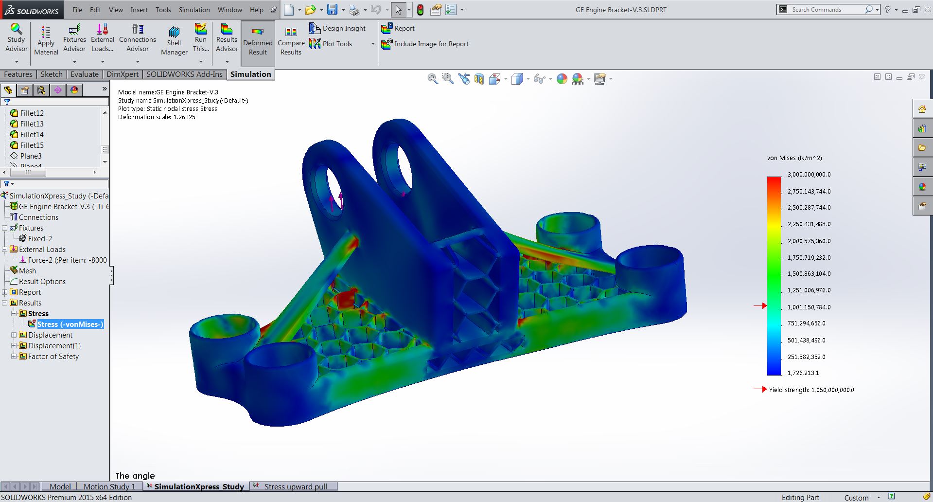
FEA is valuable where geometry and local load transfer are too complex to represent fully using simple beam calculations. In the 35-tonne project, the analysis was used to review overall stress distribution and deformation and to examine local behaviour around the lifting interfaces and welded details. The findings supported refinement of the design before fabrication.
Engineering approval is only one part of the process. Fabrication must be controlled so that the manufactured item reflects the verified design. Material identification, welding procedures, welder competence, dimensional checks and inspection requirements may all form part of the manufacturing quality plan.
Proof-load testing then provides physical evidence of the completed equipment’s response under a controlled test load. The test does not replace the design calculation; it complements it. A beam may survive a single test while still containing a design weakness, unsuitable detail or fatigue concern. Certification should therefore be supported by both engineering verification and manufacturing records.
In the United Kingdom, lifting equipment is also subject to legal duties associated with safe use and thorough examination under LOLER. Depending on the application, standards such as BS EN 13155 and project-specific lifting requirements may also be relevant. The exact compliance route should be established for each lifting accessory.
The CITA beam was successfully designed, fabricated and proof-load tested. Its delivery demonstrates the complete engineering sequence required for lifting equipment: define the duty, calculate and analyse the structure, control fabrication, inspect the finished product, complete testing and maintain traceable technical records.
Related services
Related projects
Related articles.
Finite Element Analysis: Turning Complex Structural Behaviour into Engineering Decisions
Finite Element Analysis can reveal stress concentrations, deformation and load paths that are difficult to evaluate using simplified calculations alone. Its value depends on realistic assumptions, appropriate modelling and careful engineering interpretation.
Practical Mechanical Design for Real-World Project Execution
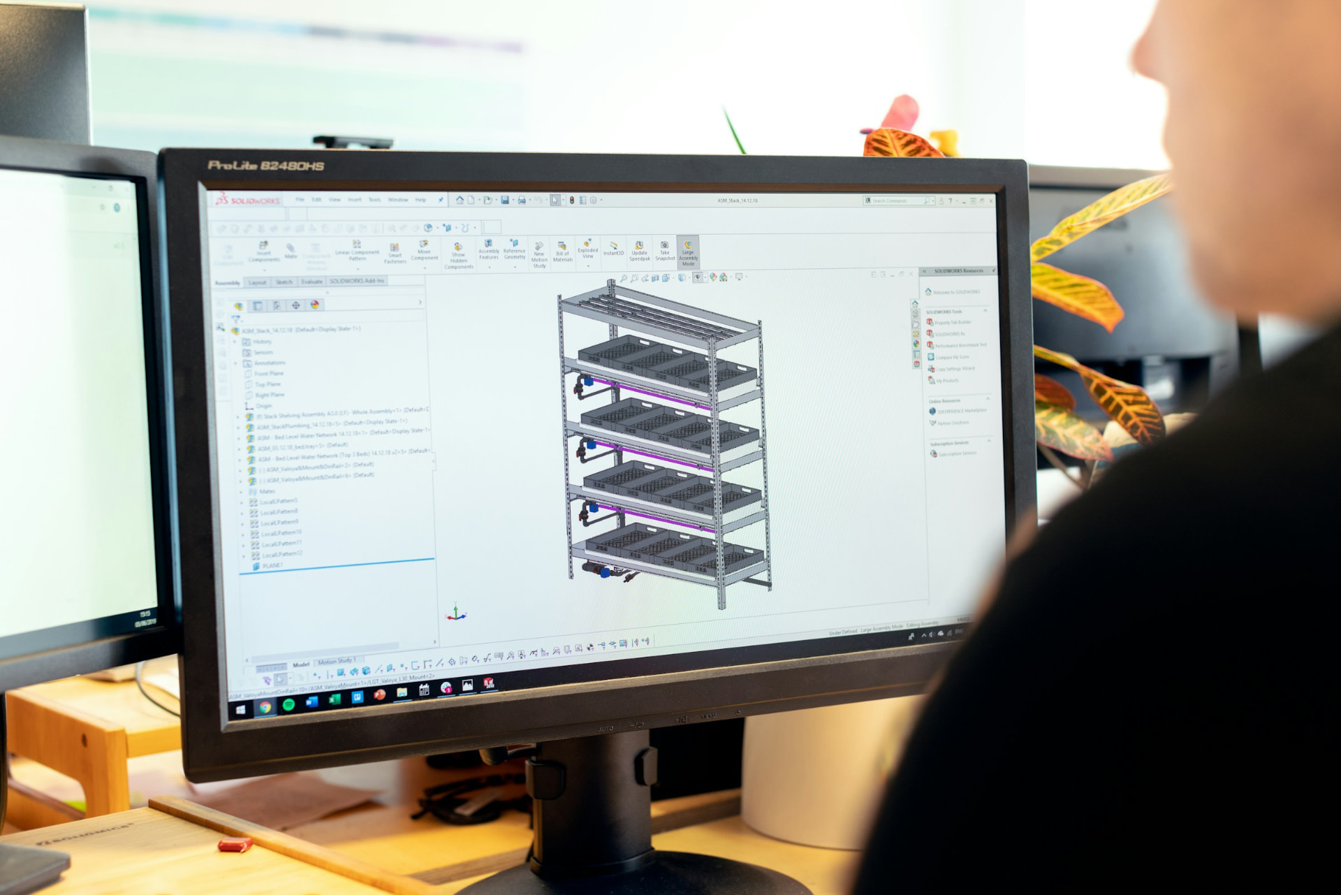
A design is not truly complete when the calculation is finished. Execution-ready mechanical design must also account for fabrication, installation, access, maintenance, inspection and the quality of the technical information issued to the people responsible for delivering the work.

Asset Integrity Priorities for Ageing Industrial Facilities
Ageing equipment should not be judged by age alone. Effective asset-integrity decisions combine inspection findings, engineering assessment, operating history and risk to determine whether equipment can remain in service, requires modification or should be replaced.
Need assurance-led engineering support on a live asset or project?
Book a technical consultation to discuss scope, risk profile, project stage, and the most appropriate support model.